Deep Space Gravity Probe
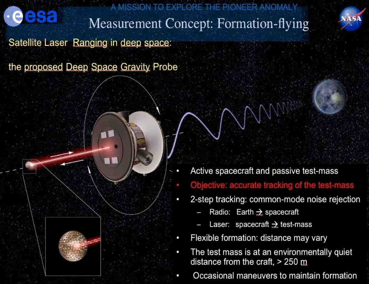 To probe gravity in the outer solar system and avoid the experimental complications such as, for example, the so-called "Pioneer Anomaly" (which is the apparent deceleration of the Pioneer 10 and 11 spacecrafts with respect to the 1/r2 force-law of about 10-9 m/sec2), a new concept of interplanetary mission has been conceived by JPL and other European research groups (including LNF, through COFIS). Deep Space Gravity Probe mission proposed to NASA and as a candidate ESA mission for Cosmic Vision, will study gravity at large distance from the Sun (up to 80 AU) and will verify the PA. Presently the formation consists of a main active satellite that will release few spherical laser-ranged test masses. The motion of a mass with respect to the Earth will be measured through radio waves from the Earth to the active satellite and through laser ranging from active satellite to test mass: when the laser beam hits the test mass, the returning beam is focused through a telescope on a detector which does not interfere with the out-coming beam. The deep space test masses are spheres equipped with CCRs. The mother-ship active spacecraft will be forward-backward symmetric compared to the solar constant AM0 on the Earth. Starting from Saturn, more than one test mass will be released by the mother-ship during the interplanetary journey, in order to test the 1/r2 force-law in different regions of the solar system.
Laser ranged test masses for deep space missions
In deep space the magnitude of Thermal Thrusts (TTs) is enormously reduced compared to those suffered by payloads near the Earth, since beyond Saturn (>10AU) the solar constant is reduced by more than two orders of magnitude compared to the Earth solar constant AM0 (1370 W/m2). TTs are proportional to the Surface/Mass (S/M) ratio and to the solar constant AM0. This means that several test masses small and light enough to be conveniently carried by an interplanetary spacecraft will have a good SLR performance keeping the TT background well under control with respect to the value of the PA. Thinking of this, the mechanical drawing and machining of the test mass prototype has been realized by the SPCM service of the Technical Division at INFN-LNF. The test mass mechanical structure has been funded by LNF, as well as the future SCF-Test campaign.
This is a spherical aluminum shell of 16 cm diameter and 2Kg weight, equipped with 102 BK-7 CCRs, each one with an active area of approximately 18 mm2. All the retroreflectors for this prototype have been purchased, individually FFDP-tested and found to meet the optical specifications. They had been all mounted on the two half-shells and for this partially equipped shell we performed optical FFDP characterization in air and isothermal conditions.
Test mass optical characterization
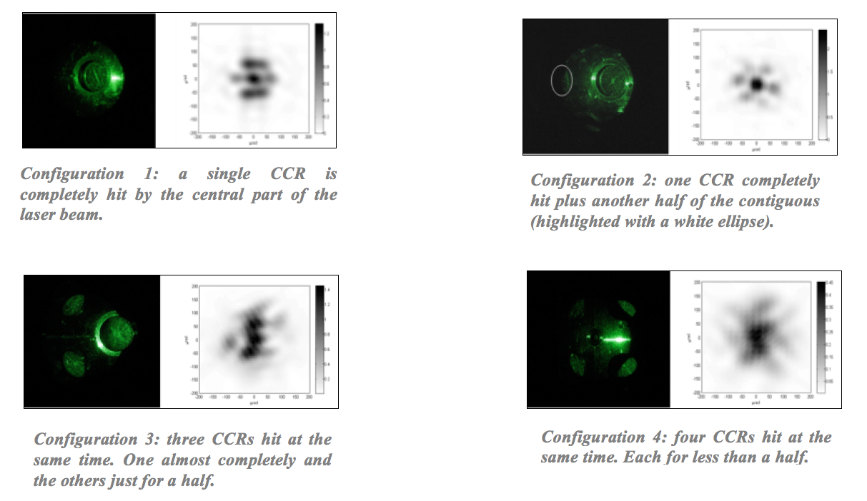
On April 2010 we started taking data with the complete test mass mounted inside the SCF cryostat. The laser beam (90 mW Nd-YAG 532nm) has a diameter of about 40mm with a Gaussian intensity distribution over the cross-section. Two different CCDs were used to take the horizontal and vertical polarized components of the FFDP separately. After the acquisition the two components were combined by the analysis software. As a first measurement phase we decided to take some FFDPs with the beam hitting several retroreflectors at the same time, in different significant configurations (like those, for example, shown below). Every plot is coupled with an image taken with a standard IR camera, showing the actual beam-retroreflectors attitude in which the FFDPs have been acquired. We have not observed only one but several CCRs mounted on a spherical surface with a small curvature radius and, thus, with:
- large (compared to the single CCR diameter) non-reflecting “dead zones”
- angles between the front face and the laser beam direction that, for some configurations, could rise to the retroreflection limit
This situation can lead to have, in some cases, more CCRs, illuminated at the same time, showing a light return similar or even lower compared to the one of a single CCR. This can be explained with two main reasons:
- the laser beam has a Gaussian decreasing trend along the radius and the single CCR is right at the center of the beam, while the three CCRs are at the edge
- the single CCR has his face perpendicular to the beam while the three CCRs are tilted
It was interesting to investigate the differences in the amount of light return among all the configurations we considered. In particular we have normalized the FFDP no longer with the Airy peak but with a new reference that is represented by the configuration in which only a single CCR is orthogonal and completely hit by the central part of the laser beam.