

Next: 2.3 Performances
Up: 2.2 Status of Subdetectors
Previous: 2.2.3 The Superconducting Solenoid
The interaction/target region and the outer tracker are assembled
on to the Detector
Support Frame, whose shape resembling a
sand-clock attributed it the Clepsydra nickname.
The Clepsydra provides endplates between which the straw tubes are mounted and
strung to tension. The drift chambers are slid
in rails made in the axial links connecting the Clepsydra radial
spokes, while the interaction/target
region and the beampipe with two pairs of permanent compensating quadrupoles
are
sustained by the two inner cylinders connecting the radial spokes on the
lateral surface of the structure.
The detectors will be installed in the Clepsydra independently of the magnet,
connected to the readout electronics and tested with cosmic rays in an assembly
laboratory. When ready in the FINUDA experimental pit, the magnet will receive
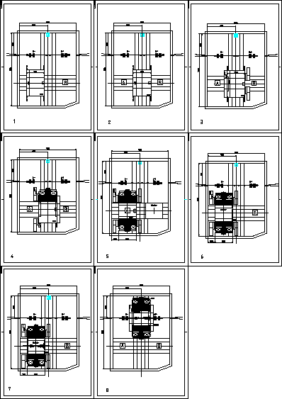
the instrumented Clepsydra via the sequence shown in fig.4, and
finally the beampipe section with the compensating quadrupoles.

Figure 4: Sequence to slide the Clepsydra (equipped with interaction/target
region and outer tracker) inside the FINUDA magnet. The beam pipe section
complete with compensator quadrupoles is inserted, finally the spectrometer
is moved in the  ring.
ring.

Figure 5:
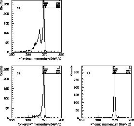
(a) Raw reconstructed momentum distribution of the prompt 270 MeV/c  ;
(b) only forward pions, i.e. not crossing back the interaction/target
region;
(c) only forward pions, after correction for the energy loss in the target
based on the
  stopping point as determined by ISIM and OSIM.
Carlos E.Piedrafita

 ring.
ring.

 ;
(b) only forward pions, i.e. not crossing back the interaction/target
region;
(c) only forward pions, after correction for the energy loss in the target
based on the
  stopping point as determined by ISIM and OSIM.