
Amplifier and pulser for
FINUDA straw tubes patch-panels
This is a preliminary version of the user manual (ver. 1.0
Jan. 2002)
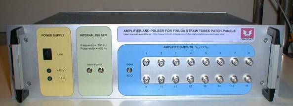
The amplifier
The amplifier has a 50 Ω input and 16 outputs with 50 Ω
output impedance. Any of the 16 channels is capable to drive a long coax line
with 100 mA maximum output current and 10 Vpp maximum output swing.
The voltage gain into a 50Ω load is 2.
The input can be AC or DC coupled by means of the jumper J1 placed on
the main board. Actually it is DC
coupled.
The internal pulser
An internal pulser has been implemented to avoid the use of an external
one. It has two NIM outputs with a
repetition rate of 300 Hz and a pulse width of 400 ns. One output can be
directly connected to the amplifier input and the other can be sent to the
trigger logic.
The fall time of the output signal is 10ns. It is enough for many purposes, i.e. for FEE
testing. If sharper edges are needed, an external pulser with better time
performances can be used.
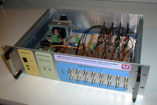
The internal pulser has been mounted on a separate board, hence it can
be replaced or improved without any interaction with the rest of the circuits.
Schematic diagrams
In this preliminary version of the user manual the schematic diagrams
has been scanned from a hand-drawn copy.
CAD-made schematics will be added in the future release of this manual.
You can download the schematics in .jpg format
·
Input stage and single channel stage
Photographs
.
Front panel
The front panel and the internal and external labels have been designed
with Microsoft Word 2000 and printed on adhesive paper. If you need to replace or modify them, you
can download the following file in .doc format.
·
Front panel and internal labels
Please send comments and questions to Fulvio Pompili: