| |
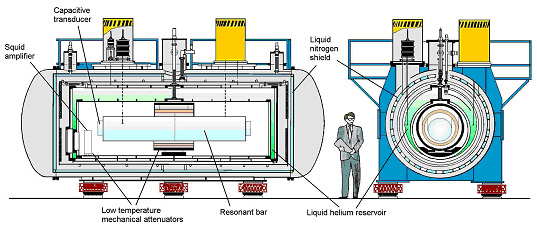
The EXPLORER detector consists of an Al5056 cylindrical bar of length L
= 2.97 m, diameter of 0.6 m and mass of 2270 kg, resonating in its first
longitudinal mode of vibration at a frequency of about 915.7 Hz at liquid-helium
temperature.
It is located at CERN laboratories (6.1E, 46.2N) and has been oriented,
since February 1990, to an azimuthal angle of 39.3, approximately parallel
to the ALLEGRO and NAUTILUS detectors. The cylindrical bar is suspended
in vacuum inside a cryostat and is kept cold at a temperature T = 2 K by
a superfluid helium bath surrounding the bar vacuum chamber.
The helium bath temperature is reduced from 4.2 to 2K by pumping on it,
and superfluid operation is very important, to reduce excess noise due to
the boiling of the liquid-helium. The cryostat consists of five horizontal
cylinders.
The external one is a steel vacuum enclosure. the second one is the liquid-nitrogen
container (460 liters) The third cylinder is a thermal shield cooled near
30 K by the gas evaporated from the liquid-helium container.
This container, consisting of the space between the fourth and the fifth
cylinder, has a capacity of 3300 liters and is made of stainless steel;
its ends are closed by large flanges (1.7 m of diameter) with indium seals.
For supefluid operation, the liquid-helium consumption is reduced to 35
liters/day (compared to 60 liters/day at 4.2K). The isolation of the bar
from external acoustic and seismic disturbances is provided by a system
of low-pass mechanical filters in cascade, with a total attenuation of -210
dB around the resonance frequency of the antenna.
The bar is suspended with a titanium cable (2 m long and 5 mm in diameter)
wrapped around the central section of the bar, the ends of this cable are
fastened to a steel ring of 1000 kg mass, which is in turn suspended by
four cables to another massive ring (1000 kg) made of bronze. This rests
on a four-cantilever-beam suspension on the bottom of the liquid-helium
container.
|
|
 |
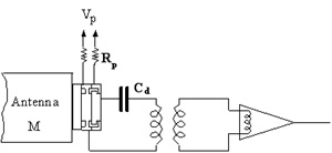
Read-out
The vibrations of the bar are converted into electrical
signals by a capacitive transducer resonating at the antenna frequency
in order to improve the energy transfer from the bar to the electronics.
The capacitive transducer, bolted to one end of the bar, consists of a
vibrating disk with mass M = 0.7 kg, and of a fixed plate. The gap between
the electrodes is 10 µm and the diameter of the plates is 13.2 cm. The
resulting capacitance is 13 nF. The transducer and the bar form a system
of two well-matched high-Q coupled oscillators with normal modes frequencies
f- = 888 Hz and f+ = 922 Hz. A mechanical amplification by a factor of
50 is provided by the large ratio between the bar and the transducer masses.
The transducer signal is fed to the input coil of a d.c. SQUID amplifier
(Quantum Design) by means of a decoupling capacitance (100 nF)
and a superconducting transformer, which provides the required impedance
matching between the high output impedance of the transducer and the low
input impedance of the SQUID. The transformer consists of a primary coil
of inductance 2.5 H and a secondary of inductance 1.6
µH, and has a coupling
factor k = 0.77. The transducer and the transformer form an electrical
circuit resonatng at a frequency νel = 1940 Hz. Thus the full system is
actually a three mode system, but the electrical mode is weakly coupled
to the mechanical modes. The output signal from the SQUID is fed to a
low-noise FET amplifier through a cooled LC resonant circuit (tank circuit)
providing the proper impedance matching, and then directly sent to the
5 kHz acquisition system, together with the timing information. |
|
Figure 1: Read-out scheme of the
detector.
|
 |
|
Vetoes
The detector is also equipped with auxiliary sensors (accelerometers,
search coil, etc.) that monitor the environment of the laboratory and
allow to veto any event, observed by the detector, that occurs in the
presence of external disturbances. A cosmic ray detector has been implemented
to measure the passage of extensive air shower or single high energy particles
in the antenna.
|
|