1.Readout Electronics
1.1 Requirements
The LAV system will mainly detect photons from kaon decays, as well as muons and pions in the beam halo. For each incoming particles the veto detectors are expected to provide a time measurement, with a ~1 ns resolution, and an energy measurement with a moderate precision of order 10%. The system should be able to operate with very low threshold, well below one minimum ionizing particle (MIP), in order to keep the detection efficiency for muons and low energy photons as high as possible.
The simplest approach would be to split the signal from the PMT�s of the lead-glasses in order to have:
- A fast measurement of the charge of the signal, using Flash ADC�s or wave-form sampling;
- A fast digitization of the signal, using a discriminator and a TDC for time measurement.
The intrinsic time resolution of the lead-glass blocks (<1ns) and the rise time of the Hamamatsu R2238 PMT (~5 ns) do not put stringent requirements on the time measurement accuracy. On the other side, concerning energy measurement, the expected deposit in the LAV stations from photons coming from p0 decays covers a very wide range, from ~10 MeV up to 30 GeV. As a reference, the PMT signal for a cosmic ray muon is shown in Figure 21.
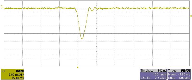
Figure 21 Typical signal from cosmic ray muons
This wide photon energy range, together with the necessity of detecting muon signals, requires operating the R2238 PMT�s at a gain of order 106. Using the measured average photoelectron yield of 0.3 p.e./MeV, one expects a ~4.5 pC charge for a MIP, corresponding to a signal amplitude of ~20 mV over 50O. On the upper part of the range, signals from 20 GeV showers can reach an amplitude of 10V over 50O. Such a signal range would be outside the possibilities of commonly used ADC chips, whose dynamic range is at most 50. On the other hand, the range of a typical amplifier-shaper-discriminator chain is of order 10.
In selecting the readout scheme, the cost and data through-put must also be considered. An approach using Flash ADCs is more expensive as the modularity of channels per readout board is low. In addition, it needs shaping electronics to stretch the signal slightly in order to have a reasonable number of samples at 40 Mhz and it imposes huge constraints on the readout board as far as the data throughput handling is concerned.
We have identified three possible strategies to cope with the wide signal amplitude range, while keeping under control the cost and complexity of the system:
1) Use a front end electronics with a clamping stage followed by an amplifier;
2) Use of multiple scales with different amplification factors for the same input signal;
3) Measure the signal height using the Time over Threshold (ToT) technique.
The requirement of signals as high as few Volts rules out most part of commonly used ASIC produced for HEP applications, such as CARIOCA, NINO, ASDQ, etc. On the other hand, the application does not justify the effort of producing a new dedicated ASIC. The idea is then to use commercial amplifier and comparator circuits, to produce a digital output signal with time duration equal to that of the analog input, exploiting the advantage of having high amplitude signals and a relatively slow rise time. Using this technique, the resulting dynamical range of the input signal is enlarged, due to the typical non-linear relationship between the ToT width and the input signal amplitude.
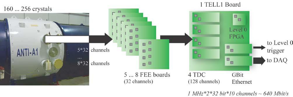
1.2 The LAV readout chain
The output signals from each station are connected to 32 channels front end electronics (FEE) cards. These FEE cards convert the analog signal from the PMT�s to a digital signal of proper width (equal to the ToT duration) using the differential LVDS standard. Then, the digital signal time of arrival and width are measured by TDC daughter-boards (using the HPTDC as described in sec. 7.2.5) mounted on a TELL1 board. The FPGA inside the TELL1 produces the time corrected from the slewing introduced by the discriminator, using a double threshold system (described in the following paragraphs), and the charge for each hit reconstructed from the ToT width and a time-charge calibration. These two informations are then sent to the following DAQ stages. L0 trigger primitives are calculated inside the TELL1 and sent to the Level 0 supervisor. The general layout is shown in Figure.