The Accumulator during installation.
The Accumulator during installation.
The DAFNE Accumulator is a small storage ring, which has been includedinto the DAFNEinjection system for the following reasons:
Schematic layout of the DAFNE Accumulator.
The Accumulator is a quasi-octagonal ring with a total length of 32.5m on the nominal trajectory. Its lattice is made of four almost achromaticarcs, each consisting of two 45 degrees full iron H-type sector dipolemagnets with a small gradient to optimise the damping distribution, a quadrupoletriplet and two sextupoles to correct the ring chromaticity. All the dipolesare powered in series. The quadrupoles are connected into three independentfamilies, the sextupoles in two families.
The DAFNE Accumulator dipole on the magnetic measurement bench.
The DAFNE Accumulator quadrupole under measurement with a rotating coilsystem.
The DAFNE Accumulator sextupole.
The electron beam coming from the Linacis injected into the ring by means of a system of two septum magnets, thefirst bending the beam by 34 degrees and the second performing the finaldeflection of 2 degrees into a special 3.5 m vacuum vessel between twoachromats. The stored beam is extracted by a mirror symmetric system placedin the opposite straight section. The positron beam follows the oppositepath. The remaining two straight sections host the pulsed kicker magnetsused to deflect the beam at injection and extraction and the R.F. cavity.
The DAFNE Accumulator R.F. cavity.
A system of 8 correctors and 10 position monitors allows a careful correctionof the closed orbit in the ring with the purpose of optimising injectionefficiency. Two synchrotron light monitors and two stored current monitorsare also part of the diagnostic system. A transverse feedback system isimplemented on the ring: it consists of a stripline pick-up and a striplinekicker.
The vacuum chamber is fully stainless steel and a pumping system consistingof 18 sputter ion pumps is designed to reach an average dynamic pressurein the ring of 5 nTorr.
| Energy | 510 MeV |
| Circumference | 32.56 m |
| Emittance | 0.26 mm.mrad |
| Horizontal betatron tune | 3.12 |
| Vertical betatron tune | 1.14 |
| R.F. frequency | 73.65 MHz |
| R.F. voltage | 200 KV |
| Bunch average current | 150 mA |
| Bunch length | 3.8 cm |
| Synchrotron radiation loss per turn | 5.2 KeV |
| Horizontal betatron damping time | 21.4 msec |
| Vertical betatron damping time | 21.4 msec |
| Longitudinal damping time | 10.7 msec |
| Number of bending magnets | 8 |
| Bending radius | 1.1 m |
| Bending angle | 45 degrees |
| Bending operating field | 1.55 T |
| Bending gradient | -0.66 T/m |
| Number of quadrupoles | 12 |
| Quadrupole bore diameter | 100 mm |
| Quadrupole operating gradient | 8 T/m |
| Quadrupole maximum gradient | 12 T/m |
| Quadrupole magnetic length | 30 cm |
| Number of sextupoles | 8 |
| Sextupole bore diameter | 108 mm |
| Sextupole operating gradient | 135 T/m2 |
| Sextupole maximum gradient | 180 T/m2 |
| Sextupole magnetic length | 10 cm |
The damping ring is fully operational and its performance has reachedthe design values with both electrons and positrons. The capture, as wellas extraction, efficiency is very near 100% and the foreseen single bunchcurrent of 120 mA can be injected in less than 1 second at 50 Hz. The maximumstored current is near to 220 mA.
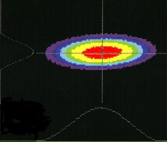
False colour image of synchrotron radiation spot from the Accumulatorbending magnet. The dotted plots on the left and bottom sides of the pictureare the vertical and horizontal linear density distributions.
During commissioning the optical parameters of the ring and the beamcharacteristics have been carefully measured, and found to be in excellentagreement with the theoretical predictions and field measurements on themagnets. The measurements of beam position at all available monitors confirmedthe reliability and precision of the alignment procedures followed by theLNF group during theinstallation of the machine: in fact the current in the dipole orbit correctorsnecessary to drive the beam on its ideal trajectory is much smaller thanits available range, and the injection and extraction efficiency does notchange when they are switched off.
Using the results of the measurements performed on the stored beam areliable optical model has been found, which is the primary tool to setthe machine at any desired working point by means of a limited number ofparameters set by the Control System. Several beam characteristics, interestingfrom the machine physics point of view, such as the bunch length and synchronousphase versus stored current, have been measured, and the results confirmedthe predictions of the simulations on the interaction of the beam withits surrounding environment.
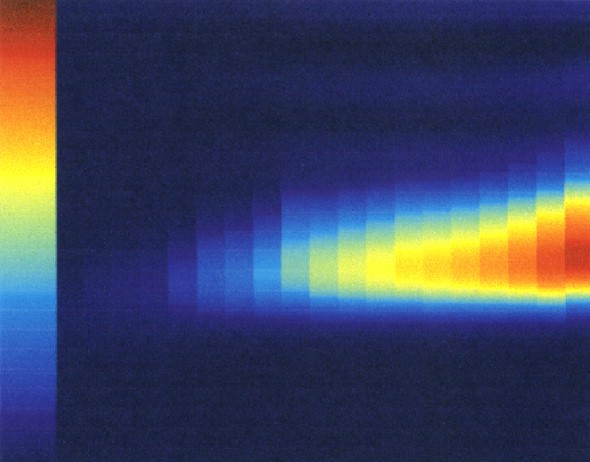
False colour representation of the bunch length measurement in the Accumulatorring. Each slice corresponds to a different stored current, increasingfrom left to right. Time is on the vertical scale. The intensity scaleis displayed on the left.
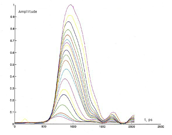
Longitudinal bunch shape measured at different current levels (0.5 to60 mA).
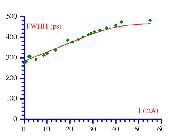
Dependence of the bunch length (full width at half maximum) on the averagecurrent. The dots are the measured values, the solid line is a numericalsimulation based on the machine impedance estimate.
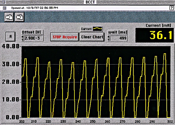
Plot of the stored current into the Accumulator during atypical Main Ring commissioning cycle. Three electron pulses are storedinto the ring before the extraction pulse. The steps on the rising sideare injection pulses, those on the fall side are due to the limited resolutionof the scope.